Twist Machine Paddle Shifter 3 Installation Guide
Overview
This guide explains how to install the third generation (Gen 3) Twist Machine Paddle Shifter. There are two major components to the system: the steering column mounted paddle shifter body containing two radio transmitters (one per paddle), and the receiver. The operation is simple:
When a paddle is pulled, an encrypted radio signal is sent to the receiver.
The signal causes the receiver to close a switch/ solid state relay (SSR).
The relay opens again when the paddle is released.
All of the action, from switch closing to relay closing, takes place within 5 milliseconds.
CAUTION
You are modifying your vehicle’s steering system.
See your vehicle repair manual and follow factory procedures for steering wheel removal and installation.
Always follow factory torque specs.
Inspect Your Paddle Shifter Kit
Your kit should have have shipped with the following:
Paddle shifter body with the color and finish you ordered.
A pre-installed, matching steering wheel adapter hub (if you ordered one).
Matching left and right paddles, along with mounting screws
A set of tools
A receiver
Wire harness
Remove the Steering Wheel and Adapter Hub.
Make sure the vehicle is on flat ground with the parking brake set.
Position steering with front wheels pointing straight ahead.
Disconnect the battery.
Remove the horn cap and disconnect horn wire.
Remove the bolts connecting steering wheel to hub.
Remove the steering wheel.
Remove the safety nut holding hub to steering shaft (this is a large 7/16-inch or ½-inch nut). Keep this nut, as well as the large spring that tensions the horn slip ring.
Using a steering wheel puller, remove adapter hub (if so equipped). The paddle shifter will replace the hub adapter.
Install the Paddle Shifter Body
We recommend leaving the paddles off of the paddle shifter body until after it has been mounted on the steering column.
Do not apply force to the paddles during installation.
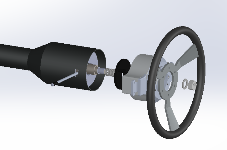
Order of components
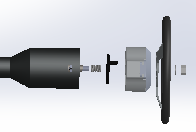
Order of components
Place the tension spring on horn slip ring and align with pass-through in the paddle shifter hub.
Align the paddle shifter with paddle mounts in the 9-3 position. The upright position on the paddle shifter has a single bolt hole in the 12 o’clock position as shown:
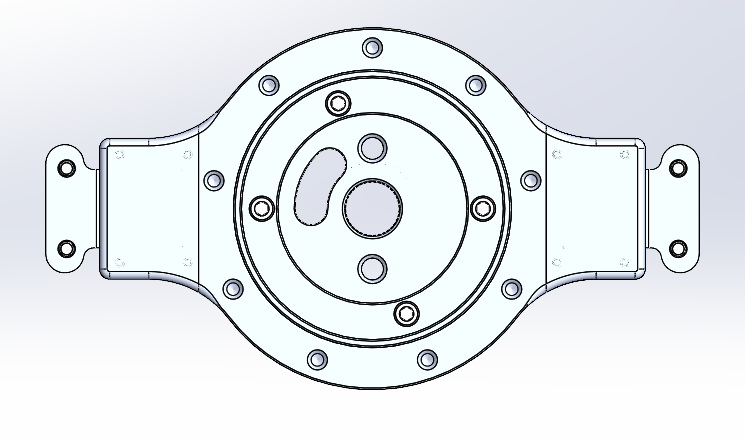
“Straight ahead” Orientation of the Paddle Shifter
Guide the assembly onto the steering shaft, being careful not to damage the turn signal cancelling cam or horn slip ring.
Install the safety nut to secure paddle shifter to steering column.
Install the Steering Wheel
For 5- or 6-bolt steering wheels ONLY, install adapter hub using 4 bolts (supplied) and installed.
Follow factory specs to install the steering wheel and connect the horn assembly.
Ensure that the paddle action will clear the steering wheel and turn signal/column stalks.
The tapered splines of the steering shaft lock the paddle shifter in place; the safety nut serves as a backup measure only. Do not over-tighten the safety nut.
Tighten the safety nut to press the tapered hub splines onto the steering shaft, allowing for no less than a 1/8-inch gap between the back of the paddle shifter hub and the steering column. Follow factory torque specifications.
Install the Paddles
Using the four provided screws and hex wrench, attach each paddle to the paddle shifter body.
The upshift / plus paddle is usually on the right, and the downshift / minus paddle is usually on the left, as shown:
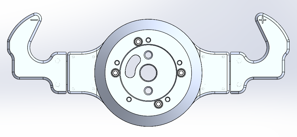
Sport Paddles with a 5 bolt hub
Mount and Connect the Receiver To Power and Ground
Find an appropriate mounting position for the receiver inside the cabin, AWAY from sources of heat or vibration.
We recommend mounting the receiver..
with a screw or bolt through the mounting tab,
or with hooks / loops adhesive on the back.
Mount the unit TEMPORARILY, as you may need to change the location after testing radio signal reception.
You may shorten the wiring and harness cover as needed, provided that the fuse is not removed from the circuit.
Connect the 12V (red) lead to a switched 10 amp-max fused power source.
Connect the black ground wire to a suitable ground.
Connect the Receiver to Your Transmission Control System
The basic connections are straightforward, regardless of the transmission controller type. Specific instructions for various transmission controllers can be found through these links:
Here are the basics:
The receiver has two wires for each paddle. A momentary switch relay connects these wires together any time the paddle is pulled.
The white/black and white/green wires connect to the switch for the left paddle.
The white/red and white wires connect to the switch for the right paddle.
Connect to the transmission controller as if you were simply connecting a pushbutton. For example, if your transmission controller needs to switch to ground for the upshift and downshift switches, then you need to connect one wire from each paddle to ground, and the other wire to the shift input like this:
Left Paddle: White/Black to ground, White/Green to downshift input
Right Paddle: White to ground, White/Red to upshift input
With the wiring completed, plug the connector on the harness into the receiver module, and press the red locking tab forward.
Receiver Pinouts
Pin Number | Function | Wire Color |
|---|---|---|
1 | +12 Power | Red |
2 | Ground | Black |
3 | Left Switch / Shift Down | White/Black |
4 | Left Switch / Shift Down | White/Green |
5 | Right Switch / Shift Up | White/Red |
6 | Right Switch / Shift Up | White |
The switch relays in the receiver are limited to 50mA maximum current. Exceeding this void the warranty and may damage the receiver.
Test Communications
Reconnect the vehicle battery and set the ignition to the ACC ON position (key ON but engine OFF).
There are four LED’s along the lower edge of the paddle shifter face: left, right, aux, and status as shown.

The status LED should be solid red when the unit has power. The left and right LED’s should blink when the corresponding paddle is pulled.
There is a small LED visible through the window on each side of the paddle shifter body. The LED will light when the corresponding paddle is pulled.
Mount the receiver and perform another test. Ensure that vehicle steering is fully operational before driving.
Using Your Paddle Shifter
To upshift, gently squeeze and release the right paddle.
To downshift, gently squeeze and release the left paddle.
Get a feel for the paddles before driving
With the key ON but engine OFF, place both hands on the steering wheel in the 10-2 position.
With thumbs and palms on the wheel, rest one or two fingers on each paddle.
GENTLY SQUEEZE AND RELEASE the right paddle to upshift, the left paddle to downshift.
DO NOT SMACK THE PADDLES.
Caring for Your Paddle Shifter
The brushed finish paddle shifter is relatively sturdy and resistant to fingerprints and dirt.
The polished finish paddle shifter is easily damaged and marred, and shows fingerprints immediately.
A soft microfiber cloth can be used to clean the body.
Avoid using caustic cleaners like soap or Simple Green on aluminum.
The polished paddle shifter can be touched up with SIMICHROME or MOTHERS WHEEL POLISH using a diaper or microfiber towel